Class I
Standard mission-interface assembly with multiple shell sizes and inserts.

SPECIAL / 1760 / 02
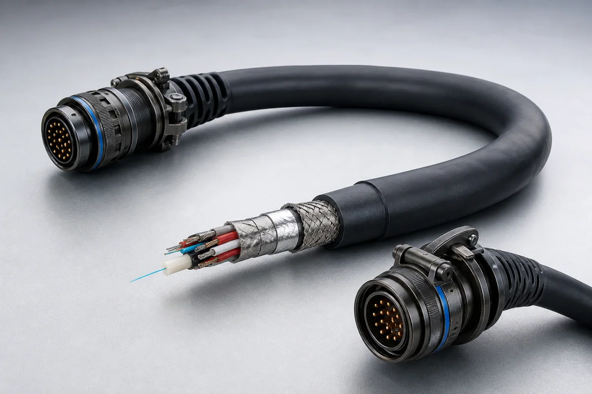
Sealed high-flex hybrid umbilicals for aircraft pylon and mission-store interfaces use controlled disconnect load, EMI shielding and long flex life for safe release and repeat maintenance.
01 / CONFIGURATION DIRECTIONS
These configurations establish a practical discussion starting point. The final product requires a controlled specification based on interface, length, installation and validation conditions.
Standard mission-interface assembly with multiple shell sizes and inserts.
Adds OM3 multimode fiber to the hybrid electrical construction.
Wire set and assembly defined to the applicable mission interface.
Solution codes support early technical discussions by aligning protocol, construction, link boundaries and application in one view.
MODEL NOTEStandard and product names identify the target interface only and do not imply unverified compliance, qualification or platform approval.
02 / PERFORMANCE PARAMETERS
The following values describe current product performance boundaries, with the applicable model, construction or test condition retained.
Matched connector assembly system
Class I / I(FO) / II
Certification test condition
Silver-plated copper braid
Class II through Class I
By part number
All standard part numbers
Dimensions and bend radii vary slightly across Class I, Class I (FO) and Class II part numbers; the applicable range is shown.
03 / TYPICAL CONSTRUCTION
Power, data, fiber, video and discrete units are separated by function.
Twists, coax, individual shields and spacing manage coupling.
Tensile load, return path and platform grounding determine the structure.
Resists fluids, abrasion, temperature, repeated deployment and mission loads.
Connectors, branches, marking, strain relief and rapid-service interfaces are integrated.
04 / SELECTION & VALIDATION
Pinout, protocols, connector and standard revision
Voltage, current, bandwidth, optical path and shield zoning
Length, diameter, mass, tensile load and bend radius
Temperature, fluids, abrasion, vibration, shock and sealing
Reel, release, mating, maintenance and storage cycles
Electrical, mechanical, environmental and system tests
Standard and product names identify the target interface only and do not imply unverified compliance, qualification or platform approval.
Ready to define a controlled specification?
Yidong Telecom can build a sample direction and validation matrix around the cable construction, termination and system boundaries.
Submit requirement checklist ↗