Multifunction integration
Isolate and arrange signal and power units for electromagnetic compatibility.

SPECIAL / 07
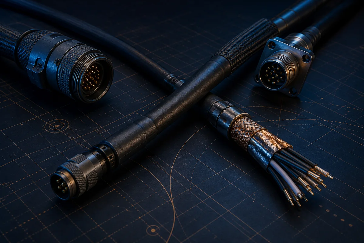
Data, control, video, discretes and power are integrated into controlled cables or assemblies for unmanned platforms, avionics and mission systems, with reinforced shielding, mechanical protection and termination.
01 / PRODUCT OVERVIEW
This information supports product direction and early technical discussions. Yidong Telecom defines final materials, dimensions and manufacturing around the actual interface, environment and validation target.
Isolate and arrange signal and power units for electromagnetic compatibility.
Reduce separate cable count while controlling diameter, weight and bend behavior.
Reinforce for vibration, temperature, abrasion, fluids and rapid connection.
Control pinout, shield grounding, connectors and test points from system documents.
02 / PRODUCT TYPES
Each type must be further defined by protocol, length, installation and environmental conditions. A category name is not a fixed specification.
Sealed hybrid links for weight-sensitive tethered platforms, combining power, control, data or fiber with strength and fluid resistance.
View specific product ↗Interconnect direction for MIL-STD-1760 interface systems; configuration, revision and tests are confirmed by project documents.
View specific product ↗03 / ENGINEERING DESIGN
High-speed data, control, video, discretes and power grouped by function.
Twists, coax, individual shields and spacing manage coupling.
Overall shield and connector-shell treatment follow the platform grounding strategy.
Abrasion jackets, braids or localized protection support the mission environment.
Mission connectors, branches, labels, strain relief and service needs integrated.
04 / SELECTION & VALIDATION
Interface-control document and pinout
Signal protocols, frequency, voltage and current
Shield zoning and platform grounding
Mass, diameter, bend and branch layout
Temperature, vibration, abrasion and fluids
Applicable revision and validation matrix
Standard names identify the target interface direction only and do not imply unverified compliance or platform approval. Project revision and acceptance methods must be defined in controlled documents.
Ready to turn a product direction into a controlled specification?
Prepare protocol, electrical, mechanical, environmental, interface and validation requirements so we can define the material, construction and sample-validation path.
Return to requirement checklist ↗