Power + fiber
Continuous power with EMI-immune optical communication.

SPECIAL / TETHER / 01
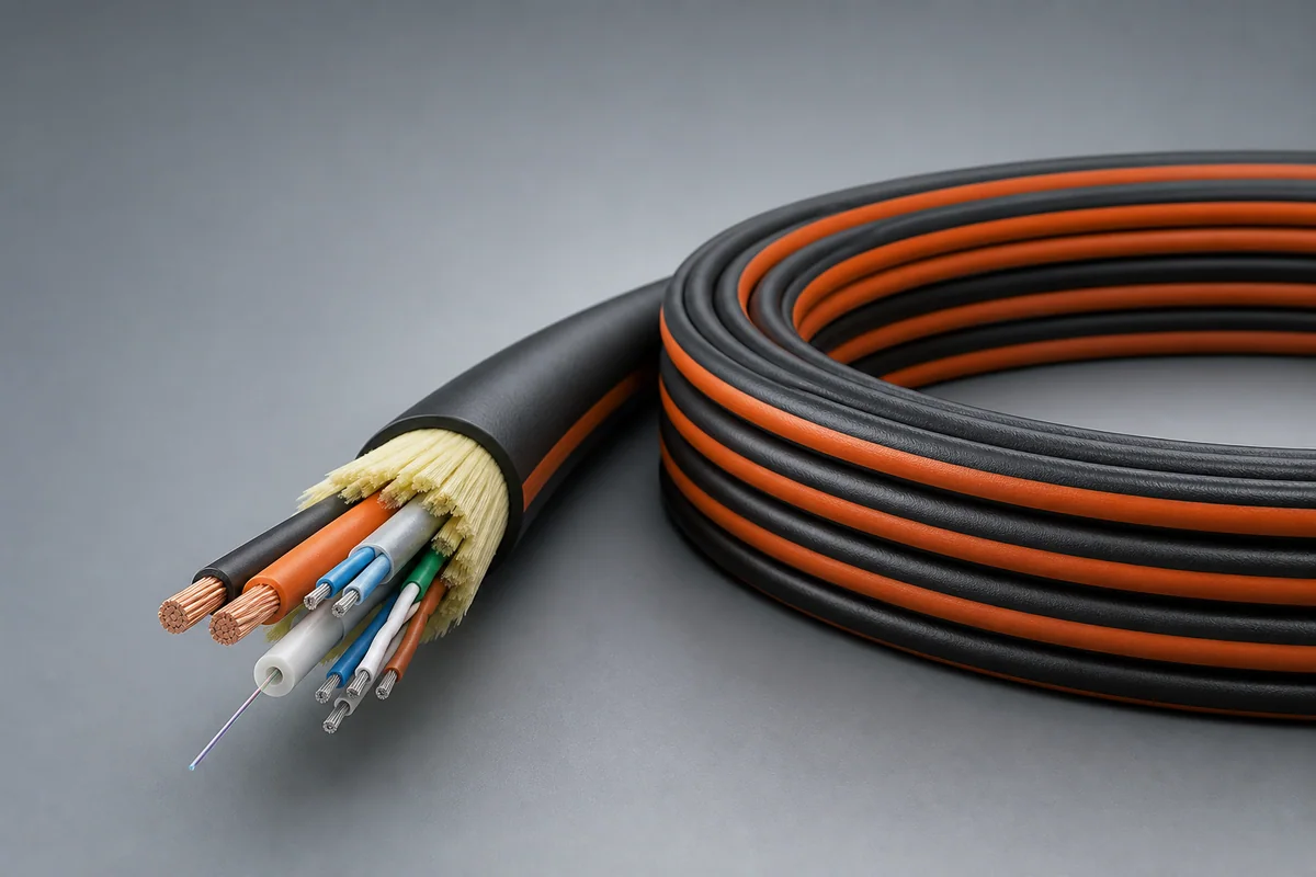
High-voltage power, data pairs and single-mode fiber are integrated into a low-mass, weatherproof, crush-resistant tether for continuous drone power and secure high-bandwidth communication.
01 / CONFIGURATION DIRECTIONS
These configurations establish a practical discussion starting point. The final product requires a controlled specification based on interface, length, installation and validation conditions.
Continuous power with EMI-immune optical communication.
Control, high-speed data and video return in one tether.
16/20/24 AWG power pairs selected by altitude and load.
Solution codes support early technical discussions by aligning protocol, construction, link boundaries and application in one view.
MODEL NOTEStandard and product names identify the target interface only and do not imply unverified compliance, qualification or platform approval.
02 / PERFORMANCE PARAMETERS
The following values describe current product performance boundaries, with the applicable model, construction or test condition retained.
Power pair / data pair
Power and data pairs
Single-mode fiber
Single-mode fiber
Power and data pairs
Versus nylon tether cables
Standard part-number direction
Power pair, data pair and fiber are separate functional units; optical attenuation may increase above 85 °C.
03 / TYPICAL CONSTRUCTION
Power, data, fiber, video and discrete units are separated by function.
Twists, coax, individual shields and spacing manage coupling.
Tensile load, return path and platform grounding determine the structure.
Resists fluids, abrasion, temperature, repeated deployment and mission loads.
Connectors, branches, marking, strain relief and rapid-service interfaces are integrated.
04 / SELECTION & VALIDATION
Pinout, protocols, connector and standard revision
Voltage, current, bandwidth, optical path and shield zoning
Length, diameter, mass, tensile load and bend radius
Temperature, fluids, abrasion, vibration, shock and sealing
Reel, release, mating, maintenance and storage cycles
Electrical, mechanical, environmental and system tests
Standard and product names identify the target interface only and do not imply unverified compliance, qualification or platform approval.
Ready to define a controlled specification?
Yidong Telecom can build a sample direction and validation matrix around the cable construction, termination and system boundaries.
Submit requirement checklist ↗