Traditional-space assembly
ESCC/NASA verification path for high-reliability missions.

SPACE / RF / 06
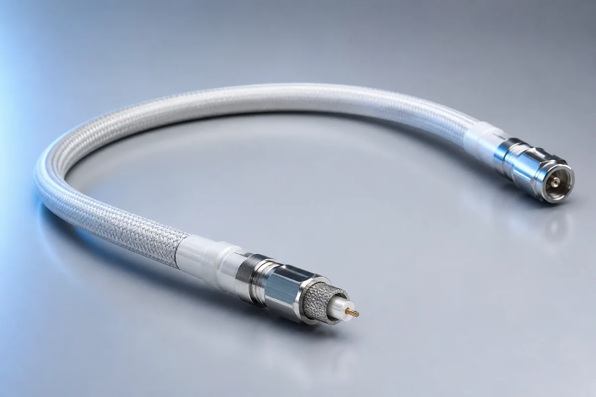
Low-loss coax, lightweight shielding, low-profile connectors and thermomechanical ruggedization operate as one assembly to maintain signal integrity and phase stability through 40 GHz during launch and orbit.
01 / CONFIGURATION DIRECTIONS
These configurations establish a practical discussion starting point. The final product requires a controlled specification based on interface, length, installation and validation conditions.
ESCC/NASA verification path for high-reliability missions.
Balances schedule, mass and mission environment validation.
Frequency, diameter, power and connector are combined.
Solution codes support early technical discussions by aligning protocol, construction, link boundaries and application in one view.
MODEL NOTEPage values do not constitute mission qualification or approval. Applicable standards, lot screening and verification levels are confirmed per project.
02 / PERFORMANCE PARAMETERS
The following values describe current product performance boundaries, with the applicable model, construction or test condition retained.
Spaceflight RF assembly family
By cable type
Type 8S example
Family typical values
Through 18 GHz
0.085–0.320 in
Sub-picosecond tolerances available
Frequency, insertion loss, diameter and connector vary by cable type; phase/time-delay matching is available by project.
03 / TYPICAL CONSTRUCTION
Material, stranding and plating are selected for resistance, strength, flex and termination.
Dielectric, thermal, vacuum-stability and processing requirements guide material selection.
Single, twisted, shielded, coaxial or multicore signal geometry is formed.
EMI, atomic oxygen, protection and mass are optimized together.
Connector, branch, strain relief, material lot and process records remain controlled.
04 / SELECTION & VALIDATION
LEO, GEO, deep space, launch phase and mission duration
Voltage, current, protocol, frequency, impedance and core count
Mass per meter, diameter, bend radius and route
Vacuum, thermal cycle, radiation, ATOX, vibration and shock
Connector, branch, lacing, ground and installation process
Applicable ESCC/NASA documents, first article, lot and traceability
Page values do not constitute mission qualification or approval. Applicable standards, lot screening and verification levels are confirmed per project.
Ready to define a controlled specification?
Yidong Telecom can build a sample direction and validation matrix around the cable construction, termination and system boundaries.
Submit requirement checklist ↗