Standard clean direction
For clean automated equipment and controlled horizontal or vertical motion.

FLEX / FLAT / 01
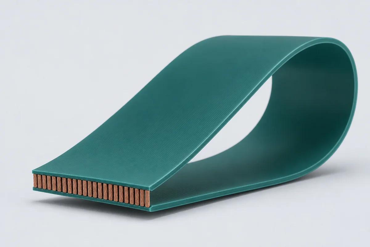
Parallel low-profile constructions for repeated planar motion, combining compact routing with conductor-position control, low internal stress and equipment-specific termination.
01 / CONFIGURATION DIRECTIONS
These configurations establish a practical discussion starting point. The final product requires a controlled specification based on interface, length, installation and validation conditions.
For clean automated equipment and controlled horizontal or vertical motion.
For ESD-sensitive handling, inspection and packaging equipment.
Pitch and conductor layout defined around insulation-displacement termination where appropriate.
Solution codes support early technical discussions by aligning protocol, construction, link boundaries and application in one view.
MODEL NOTEFlex life and clean performance are functions of radius, stroke, acceleration, load, installation and material configuration and must be validated on the target equipment.
02 / PERFORMANCE PARAMETERS
The following values describe current product performance boundaries, with the applicable model, construction or test condition retained.
Dynamic application
Standard and antistatic configurations
Custom flat construction
Dynamic flexing
BR 50 mm, up to 4 g
Standard version
Cleanroom application configuration
Antistatic version
Dynamic life is based on a 50 mm bend radius and up to 4 g; IDC and antistatic versions have their own electrical and environmental values.
03 / TYPICAL CONSTRUCTION
Stranding balances electrical resistance and fatigue behavior.
Low-stress material protects conductors while maintaining pitch.
Places conductors near the neutral plane and controls relative movement.
Stabilizes width and manages tension, friction and local stress.
Supports repeated travel and selected clean-environment direction.
04 / SELECTION & VALIDATION
Signal, power, grounding and optional optical/pneumatic elements
Width, thickness, pitch and conductor count
Stroke, speed, acceleration, radius and cycles
Horizontal, vertical and guided/free-span routing
Cleanliness, ESD, temperature, humidity and vacuum
IDC, solder, crimp or custom connector assembly
Flex life and clean performance are functions of radius, stroke, acceleration, load, installation and material configuration and must be validated on the target equipment.
Ready to define a controlled specification?
Yidong Telecom can build a sample direction and validation matrix around the cable construction, termination and system boundaries.
Submit requirement checklist ↗