Standard clean version
For clean automation and linear-motion equipment.

FLEX / TRACKLESS / 03
Lightweight flat self-supporting cable direction for replacing conventional cable carriers in clean motion platforms, reducing vibration, particles, occupied volume and maintenance complexity.
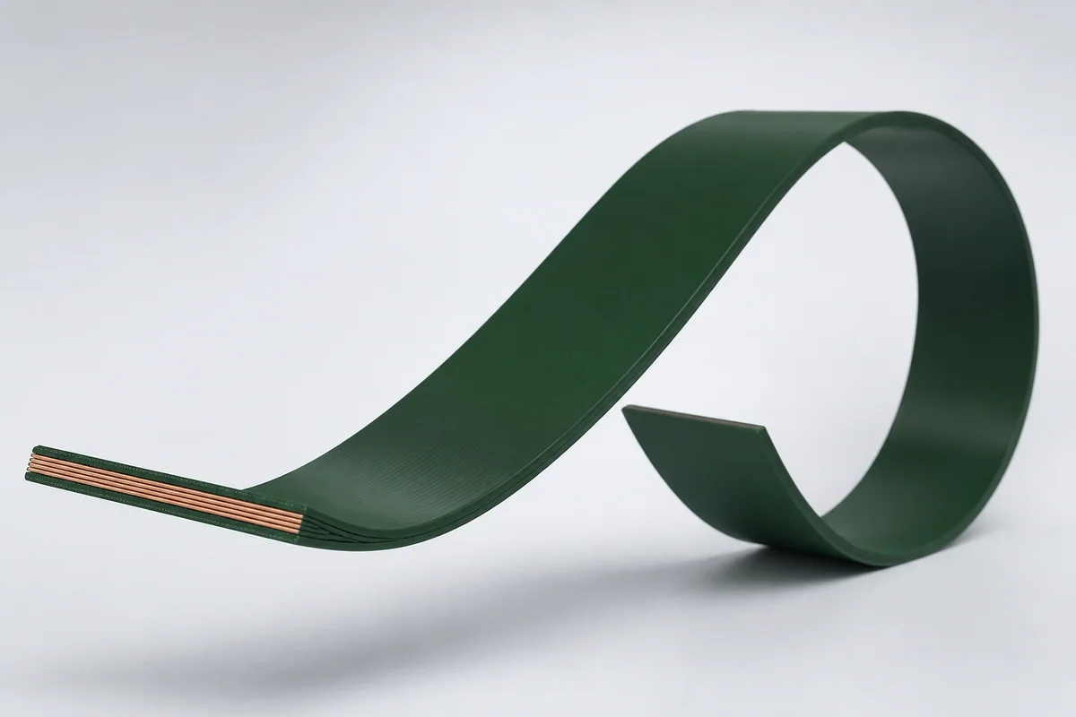
01 / CONFIGURATION DIRECTIONS
These configurations establish a practical discussion starting point. The final product requires a controlled specification based on interface, length, installation and validation conditions.
For clean automation and linear-motion equipment.
For ESD-sensitive packaging, inspection and pick-and-place tools.
Width, length and fixtures defined around travel, clamps and machine mounting points.
Solution codes support early technical discussions by aligning protocol, construction, link boundaries and application in one view.
MODEL NOTEA trackless solution is tightly coupled to machine mechanics and must be validated with the actual travel, orientation, load and mounting method.
02 / PERFORMANCE PARAMETERS
The following values describe current product performance boundaries, with the applicable model, construction or test condition retained.
Trackless dynamic application
Trackless construction
Flat construction
Dynamic flexing
BR 50 mm, up to 4 g
Standard version
Cleanroom application configuration
Antistatic version
Dynamic life applies at a 50 mm bend radius and up to 4 g; cleanroom and antistatic performance must be verified for the selected version.
03 / TYPICAL CONSTRUCTION
Signal, power, optical or pneumatic elements are combined as required.
Maintains element position and reduces coupling during motion.
Material and geometry control sag, vibration and springback.
Reduces motion resistance and particle generation.
End clamps, base plates and guides are co-designed with the cable.
04 / SELECTION & VALIDATION
Horizontal/vertical direction, stroke, speed and acceleration
Free span, width, load and allowable sag
Vibration, springback and repeatability sensitivity
Signal, power, fiber and pneumatic content
Cleanliness, vacuum, ESD, temperature and humidity
Base plate, clamps, fixed points and service space
A trackless solution is tightly coupled to machine mechanics and must be validated with the actual travel, orientation, load and mounting method.
Ready to define a controlled specification?
Yidong Telecom can build a sample direction and validation matrix around the cable construction, termination and system boundaries.
Submit requirement checklist ↗