Internal equipment interconnect
For board, module and enclosure paths with tight routing.

RF / GENERAL / 01
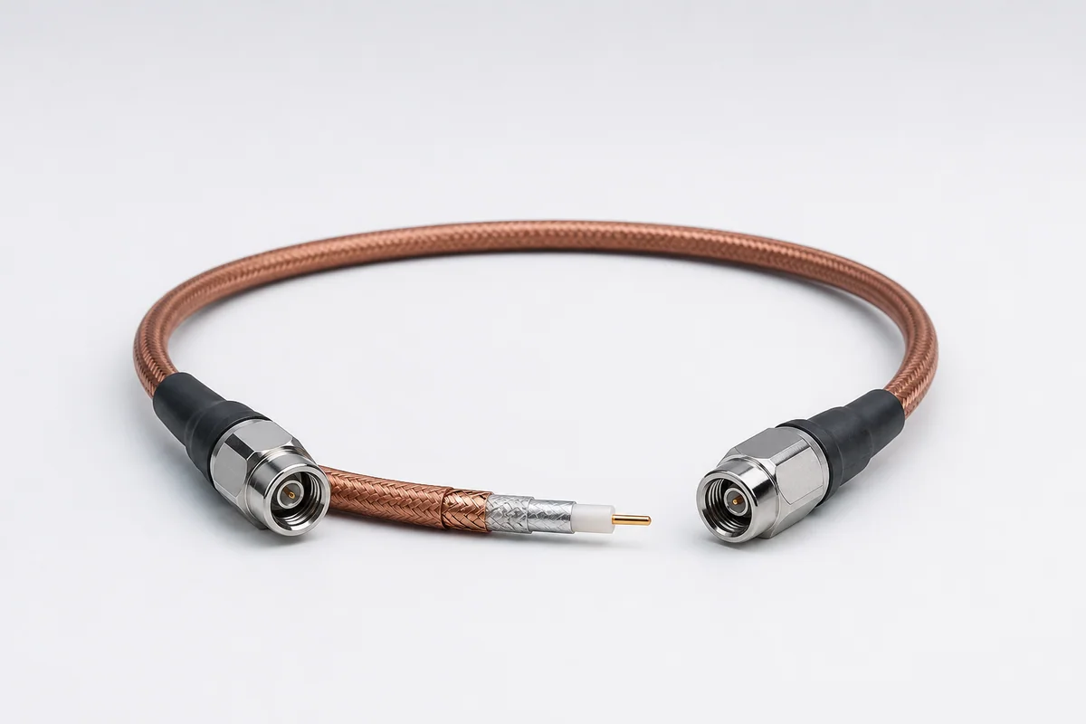
Flexible low-loss RF interconnect direction for internal equipment, module-to-module, bench and environmental-test links, balancing compact routing, shielding and long-term amplitude/phase stability.
01 / CONFIGURATION DIRECTIONS
These configurations establish a practical discussion starting point. The final product requires a controlled specification based on interface, length, installation and validation conditions.
For board, module and enclosure paths with tight routing.
For repeat measurements on benches, load boards and automated test equipment.
For chamber, thermal-vacuum or remote-instrument paths where temperature and length change are evaluated.
Solution codes support early technical discussions by aligning protocol, construction, link boundaries and application in one view.
MODEL NOTEFrequency, loss and stability values are supplied only after cable type, length, connector and test conditions are defined.
02 / PERFORMANCE PARAMETERS
The following values describe current product performance boundaries, with the applicable model, construction or test condition retained.
General-purpose microwave/RF assembly family
Applicable assembly configuration
Selected by assembly category
Catalog standard configurations
Sub-picosecond tolerances available
Configured by frequency and interface
Frequency, connector and standard length are combined by assembly family; final insertion loss and VSWR must be based on the selected assembly part number.
03 / TYPICAL CONSTRUCTION
Size and finish selected for frequency, flex and termination.
Establishes target impedance and controls dielectric loss.
Provides return path, shielding and mechanical stability.
Matches bend, abrasion, temperature and chemical environment.
Optimized with transition, strain relief and assembly process.
04 / SELECTION & VALIDATION
Minimum/maximum frequency and critical test points
Assembly length, tolerance and routing
Allowable insertion loss, return loss and shielding target
Amplitude/phase behavior with bend, temperature and time
Bend radius, motion, abrasion and strain relief
Series, gender, orientation and mounting
Frequency, loss and stability values are supplied only after cable type, length, connector and test conditions are defined.
Ready to define a controlled specification?
Yidong Telecom can build a sample direction and validation matrix around the cable construction, termination and system boundaries.
Submit requirement checklist ↗