Laboratory test assembly
For bench instruments and R&D measurement, emphasizing handling flexibility and repeatability.

RF / RUGGED TEST / 02
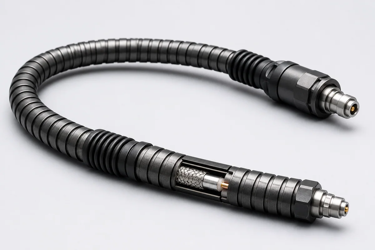
Cable, connector and strain-relief systems reinforced for frequent flexing, mating, twisting and accidental mechanical loads in laboratories, production lines and field testing.
01 / CONFIGURATION DIRECTIONS
These configurations establish a practical discussion starting point. The final product requires a controlled specification based on interface, length, installation and validation conditions.
For bench instruments and R&D measurement, emphasizing handling flexibility and repeatability.
For frequent movement and mating, emphasizing service life, connector protection and downtime.
Reinforced toward dust, moisture, abrasion and wide-temperature strain relief.
Solution codes support early technical discussions by aligning protocol, construction, link boundaries and application in one view.
MODEL NOTERuggedization does not permit unlimited bending or crushing; service life must be validated against frequency, radius, load and handling practice.
02 / PERFORMANCE PARAMETERS
The following values describe current product performance boundaries, with the applicable model, construction or test condition retained.
Type CX test assembly
Applicable constructions
Type CX supports 110 GHz
Families through 70 GHz
110 GHz family
Sub-picosecond tolerances available
The 110 GHz limit applies to Type CX; continuous flex life applies only to the specified constructions.
03 / TYPICAL CONSTRUCTION
Controls impedance, loss and phase change after bending.
Distributes stepping, pinching and localized bend loads.
Reduces damage caused by twist, knots and over-bending.
Supports benches, equipment edges and field use.
Improves tensile, repeated-mating and strain-relief performance.
04 / SELECTION & VALIDATION
Target band and measurement dynamic range
Allowable amplitude/phase variation with bend and temperature
Flex frequency, mate cycles and handling pattern
Assembly length, drag path and minimum bend radius
Temperature, dust, humidity, chemicals and vacuum
Interface, adapters, torque and protection
Ruggedization does not permit unlimited bending or crushing; service life must be validated against frequency, radius, load and handling practice.
Ready to define a controlled specification?
Yidong Telecom can build a sample direction and validation matrix around the cable construction, termination and system boundaries.
Submit requirement checklist ↗