Loss & power
Evaluate link budget and thermal load from frequency, length, conductor and dielectric loss.

RF / 03
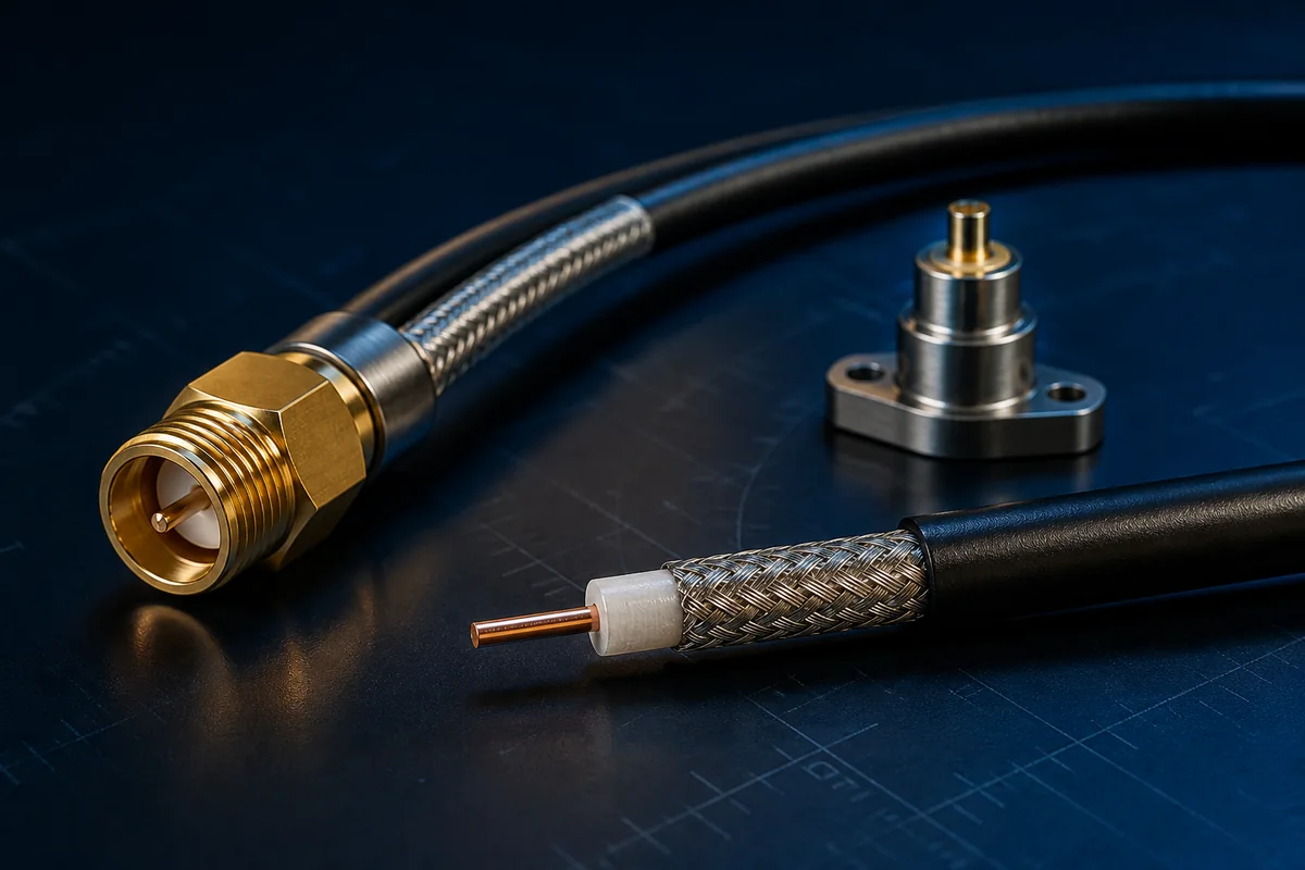
Controlled coaxial structures, low-loss dielectrics, stable shields and precision terminations for test, wireless and airborne systems—engineered to manage insertion loss, reflection and phase change.
01 / PRODUCT OVERVIEW
This information supports product direction and early technical discussions. Yidong Telecom defines final materials, dimensions and manufacturing around the actual interface, environment and validation target.
Evaluate link budget and thermal load from frequency, length, conductor and dielectric loss.
Control coax geometry, connector transition and assembly dimensions.
Manage electrical-length drift from temperature, bending and materials.
Design external protection for vibration, wear, sealing and pull loads.
02 / PRODUCT TYPES
Each type must be further defined by protocol, length, installation and environmental conditions. A category name is not a fixed specification.
Balanced performance, flexibility, cost and assembly for internal equipment or rack connections.
View specific product ↗Reinforced jacket, strain relief and terminations for vibration, temperature change and tight routing.
View specific product ↗Frequent laboratory and production connection with emphasis on durability and repeatability.
View specific product ↗Precision measurement paths focused on amplitude, phase, bend sensitivity and reconnect repeatability.
View specific product ↗Electrical and sealed-interface co-design for moisture or gas isolation requirements.
View specific product ↗03 / ENGINEERING DESIGN
Geometry, finish and plating selected for frequency, resistance, flex and termination.
Maintains conductor position and impedance while controlling dielectric loss.
Braid, foil, tubular or composite return path and shielding.
Selected for flexibility, abrasion, sealing, temperature or airframe use.
Cable, connector and strain relief terminated and tested as one assembly.
04 / SELECTION & VALIDATION
Frequency range and impedance
Allowable loss, return loss and phase change
CW or pulse power
Assembly length and connector types
Minimum bend radius and motion
Temperature, vibration, sealing and protection
RF performance depends directly on frequency, length, connectors, routing state and test method. Specific values are established after the assembly configuration is defined.
Ready to turn a product direction into a controlled specification?
Prepare protocol, electrical, mechanical, environmental, interface and validation requirements so we can define the material, construction and sample-validation path.
Return to requirement checklist ↗