Port-extension assembly
Stable handling connection between a VNA port and device under test.

RF / VNA / 03
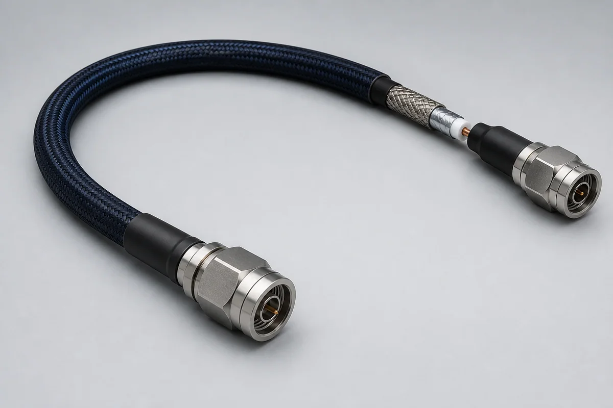
Precision vector-network-analyzer paths using low-springback flexible construction, precision connectors and controlled assembly to improve reconnect repeatability and measurement stability between calibrations.
01 / CONFIGURATION DIRECTIONS
These configurations establish a practical discussion starting point. The final product requires a controlled specification based on interface, length, installation and validation conditions.
Stable handling connection between a VNA port and device under test.
For fast instrument-side adaptation and repeated connection; exact interface is confirmed from the analyzer.
Length, connectors and handling rules defined for critical amplitude and S-parameter measurements.
Solution codes support early technical discussions by aligning protocol, construction, link boundaries and application in one view.
MODEL NOTEInterfaces and frequency ranges are selection directions only; precision capability must be confirmed with the analyzer, calibration kit, adapters and complete uncertainty budget.
02 / PERFORMANCE PARAMETERS
The following values describe current product performance boundaries, with the applicable model, construction or test condition retained.
Precise, repeatable VNA measurement
Mechanical test condition
At minimum bend radius
FB / FD / FE / FF families
25 / 38 / 48 in
Selected by VNA interface and frequency
Ruggedized armor construction
Different VNA assembly types cover 26.5–70 GHz; crush and flex-life values are listed against the applicable test conditions.
03 / TYPICAL CONSTRUCTION
Controls impedance, insertion/return loss and electrical length.
Reduces geometry and dielectric change from bend and temperature.
Protects the measurement core from laboratory mechanical damage.
Improves placement and reduces force applied to the DUT.
Controls interface geometry, torque and adapter boundary.
04 / SELECTION & VALIDATION
Analyzer port and target maximum frequency
Interface size, gender, NMD/conventional direction and adapters
Reach, bend path and electrical-length requirement
Insertion loss, return loss, phase, group delay or device behavior
Reference plane, use frequency and allowable drift
Torque, mating, storage and minimum bend radius
Interfaces and frequency ranges are selection directions only; precision capability must be confirmed with the analyzer, calibration kit, adapters and complete uncertainty budget.
Ready to define a controlled specification?
Yidong Telecom can build a sample direction and validation matrix around the cable construction, termination and system boundaries.
Submit requirement checklist ↗