Types 04 / 65 / 6E
18 GHz families selected by loss, diameter and bend radius.

RF / AIRFRAME / 04
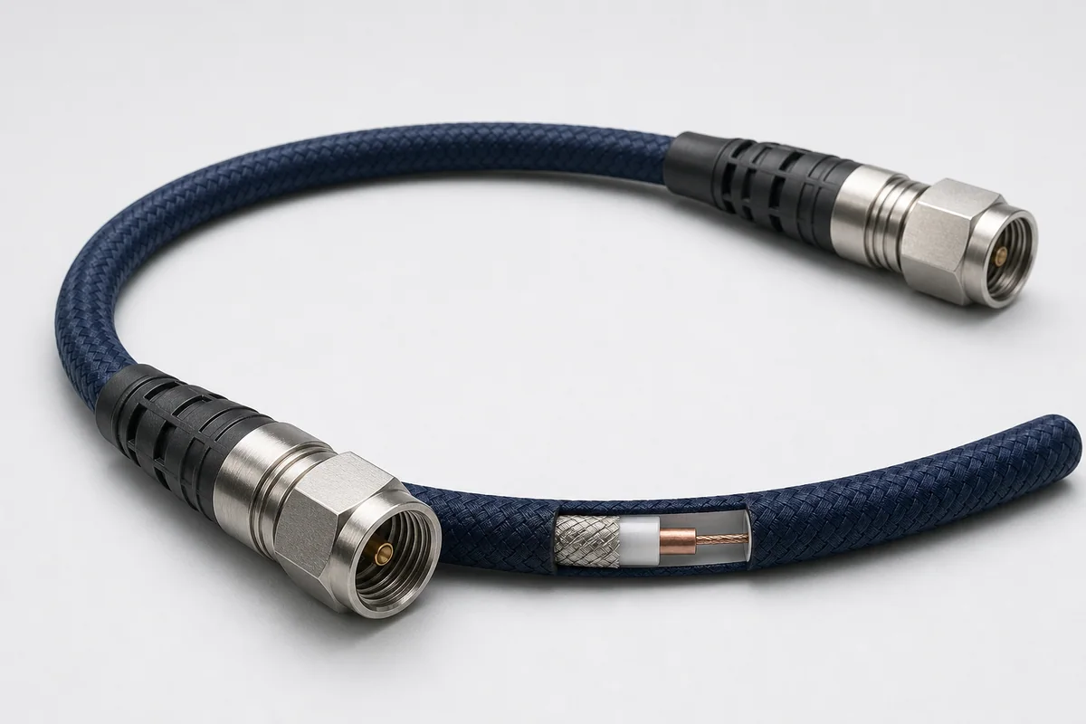
Lightweight flexible 50-ohm RF assemblies for civil and military aircraft, maintaining link performance through 40 GHz across routing, maintenance, vibration and flight conditions.
01 / CONFIGURATION DIRECTIONS
These configurations establish a practical discussion starting point. The final product requires a controlled specification based on interface, length, installation and validation conditions.
18 GHz families selected by loss, diameter and bend radius.
Compact 40 GHz airborne assembly.
Ends configured to equipment interface and maintenance strategy.
Solution codes support early technical discussions by aligning protocol, construction, link boundaries and application in one view.
MODEL NOTERF values vary by cable type, frequency, length and connector. The finished assembly must be tested in its defined configuration.
02 / PERFORMANCE PARAMETERS
The following values describe current product performance boundaries, with the applicable model, construction or test condition retained.
By cable type
At maximum frequency, straight connector
At maximum frequency, straight connector
At each type's maximum frequency
Shielding through 18 GHz
By cable type
MIL-T-81490 load condition
Types 04, 65, 6E and 6G differ in frequency, loss, diameter and bend radius.
03 / TYPICAL CONSTRUCTION
Solid or stranded geometry is selected for frequency, power, flex and termination.
Maintains 50-ohm coaxial geometry while reducing high-frequency dielectric loss.
A stable return and shielding path limits impedance change after installation.
Resists crush, abrasion, bending, vapor and aircraft-fluid ingress.
Interface, direction, length and service strategy complete the assembly.
04 / SELECTION & VALIDATION
Maximum frequency, CW/pulse power and link loss
VSWR, insertion loss, phase, delay and thermal stability
Equipment spacing, service loop, route and matching
Diameter, mass, bend radius, crush and maintenance loads
Temperature, vibration, vapor, fuel, fluids and EMI
SMA, TNC, 2.92 mm and replaceable-interface options
RF values vary by cable type, frequency, length and connector. The finished assembly must be tested in its defined configuration.
Ready to define a controlled specification?
Yidong Telecom can build a sample direction and validation matrix around the cable construction, termination and system boundaries.
Submit requirement checklist ↗