Aerospace power electronics
For high-power-density inverter, power-module and DC-link capacitor directions.

POWER / FILM / 01
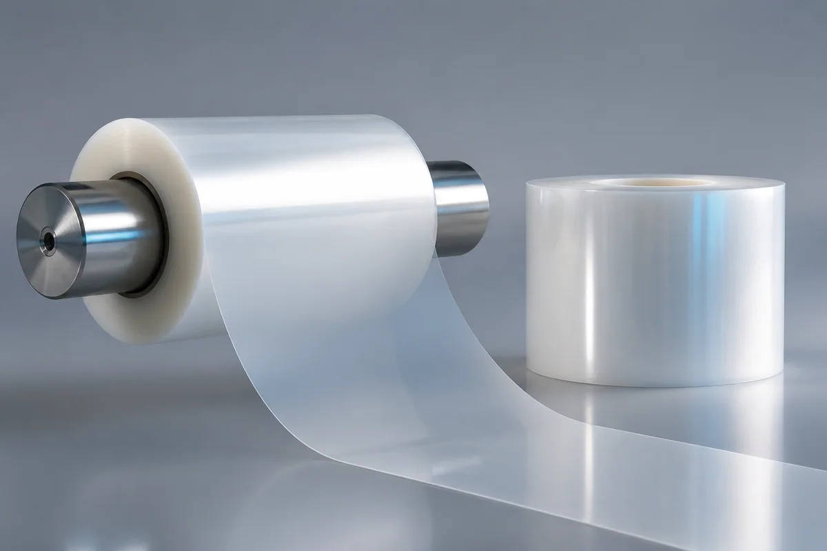
Low-loss engineered fluoropolymer film for aerospace power electronics and harsh-environment capacitors, maintaining voltage and capacitance stability under heat, field stress and long energized duty.
01 / CONFIGURATION DIRECTIONS
These configurations establish a practical discussion starting point. The final product requires a controlled specification based on interface, length, installation and validation conditions.
For high-power-density inverter, power-module and DC-link capacitor directions.
For long-life systems with limited cooling or elevated ambient temperature.
Film and metallization are defined by capacitance, voltage, width and package.
Solution codes support early technical discussions by aligning protocol, construction, link boundaries and application in one view.
MODEL NOTEFilm values are material-level data. Finished-capacitor capability also depends on metallization, winding, package, cooling and electric-field design.
02 / PERFORMANCE PARAMETERS
The following values describe current product performance boundaries, with the applicable model, construction or test condition retained.
Film material
Material system
Standard value
Material property
Tanδ
At 25 °C
These are high-temperature capacitor-film material properties; finished-capacitor values still depend on metallization, winding and package design.
03 / TYPICAL CONSTRUCTION
Engineered fluoropolymer film forms the low-loss dielectric core.
Metal layers are defined around capacitance, current density and self-healing.
Tension, alignment and edge control maintain thickness and field consistency.
Low-resistance interfaces control pulse current and localized heating.
Potting, enclosure and thermal path support vibration and elevated temperature.
04 / SELECTION & VALIDATION
Capacitance, working voltage, ripple current and peak power
Continuous temperature, hot spots and thermal cycling
Dielectric loss, ESR and allowable temperature rise
Film thickness, winding size, package and mass
Metallization, winding, end spray and encapsulation
Voltage, temperature, vibration and capacitance drift
Film values are material-level data. Finished-capacitor capability also depends on metallization, winding, package, cooling and electric-field design.
Ready to define a controlled specification?
Yidong Telecom can build a sample direction and validation matrix around the cable construction, termination and system boundaries.
Submit requirement checklist ↗