Current & temperature
Evaluate conductor, ambient temperature, bundling and heat dissipation together.

POWER / 04
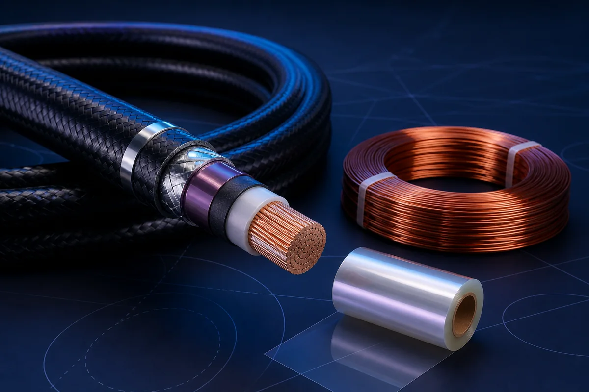
Conductor cross-section, plating, insulation thickness, thermal path and installation are co-optimized for aerospace power, windings, power modules and dense feeder applications.
01 / PRODUCT OVERVIEW
This information supports product direction and early technical discussions. Yidong Telecom defines final materials, dimensions and manufacturing around the actual interface, environment and validation target.
Evaluate conductor, ambient temperature, bundling and heat dissipation together.
Select material and thickness from voltage, transient and environmental constraints.
Quantify tradeoffs among safety margin, protection, diameter and mass.
Control crimp, solder, plating and contact stability through thermal cycling.
02 / PRODUCT TYPES
Each type must be further defined by protocol, length, installation and environmental conditions. A category name is not a fixed specification.
Dielectric and structural film direction with focus on electrical behavior, thickness consistency, temperature and processing.
View specific product ↗Weight, diameter, thermal, mechanical protection and electrical safety balanced for aerospace environments.
View specific product ↗Winding wire for motors, transformers and inductors, matched to enamel, winding, thermal and corona needs.
View specific product ↗Primary equipment or platform power paths engineered around current, drop, temperature, shielding and termination.
View specific product ↗03 / ENGINEERING DESIGN
Solid, bundled or stranded copper-based conductor selected for resistance, flex and termination.
Provides voltage, temperature, abrasion and environmental performance.
Added where EMI, fault-current or grounding paths require it.
Braid, tapes, jackets or layered construction for installation loads.
Validated with terminal temperature, crimp window and equipment interface.
04 / SELECTION & VALIDATION
Working voltage, continuous and peak current
Allowable voltage drop and temperature rise
Ambient temperature and bundle installation
Diameter, weight and flex
Terminal, crimp or solder process
Abrasion, flame, shielding and standards
Ampacity cannot be defined from conductor size alone. Ambient temperature, bundling, cooling, termination and safety standards must be assessed together.
Ready to turn a product direction into a controlled specification?
Prepare protocol, electrical, mechanical, environmental, interface and validation requirements so we can define the material, construction and sample-validation path.
Return to requirement checklist ↗