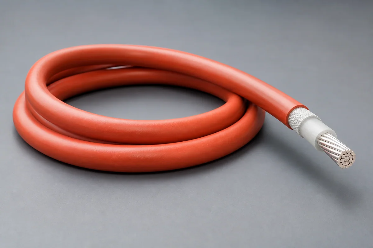
High-voltage single feeder
For primary power distribution and high-current equipment.

POWER / FEEDER / 04
High-voltage, wide-temperature, low-springback feeder paths for aircraft main power and electrification systems, controlling partial discharge, thermal aging, abrasion and constrained routing.
01 / CONFIGURATION DIRECTIONS
These configurations establish a practical discussion starting point. The final product requires a controlled specification based on interface, length, installation and validation conditions.
For primary power distribution and high-current equipment.
Controls EMI and return path alongside high-voltage delivery.
Gauge, length, terminals and routing form a complete assembly.
Solution codes support early technical discussions by aligning protocol, construction, link boundaries and application in one view.
MODEL NOTEAmpacity, voltage and temperature rise must be defined with gauge, length, altitude, bundling, cooling and termination conditions.
02 / PERFORMANCE PARAMETERS
The following values describe current product performance boundaries, with the applicable model, construction or test condition retained.
260 °C at 25 kft (7.6 km)
260 °C at sea level
Test value
At 23 °C
Mechanical/environmental range
Endurance condition
Mechanical tests
Altitude, voltage and temperature values apply to their stated combinations and are not interchangeable as continuous ratings for arbitrary conditions.
03 / TYPICAL CONSTRUCTION
Gauge, stranding and plating are selected for resistance, flex and termination.
Thin-wall high-temperature material establishes voltage, PD and abrasion margin.
Grading, shielding and return paths are added for high-voltage or EMI needs.
Tapes, braid or jacket improve cut-through, wear and installation durability.
Crimp, solder, connector and thermal-cycle interfaces are controlled together.
04 / SELECTION & VALIDATION
Continuous/peak voltage, current, frequency and partial-discharge boundary
Length, conductor section, resistance and allowable voltage drop
Ambient, bundling, cooling and temperature rise
Diameter, mass, bend radius, vibration and abrasion
Fluids, humidity, flame, smoke/toxicity or vacuum
Terminal, crimp window, connector and strain relief
Ampacity, voltage and temperature rise must be defined with gauge, length, altitude, bundling, cooling and termination conditions.
Ready to define a controlled specification?
Yidong Telecom can build a sample direction and validation matrix around the cable construction, termination and system boundaries.
Submit requirement checklist ↗