Aircraft equipment wire
For airborne power and EWIS with mass, diameter and safety margin balanced.

POWER / HPW / 02
Temperature-resistant, chemically inert and abrasion-resistant engineered fluoropolymer insulation supports stable high-voltage, lightweight and long-term material reliability in current and next-generation aircraft electrical systems.
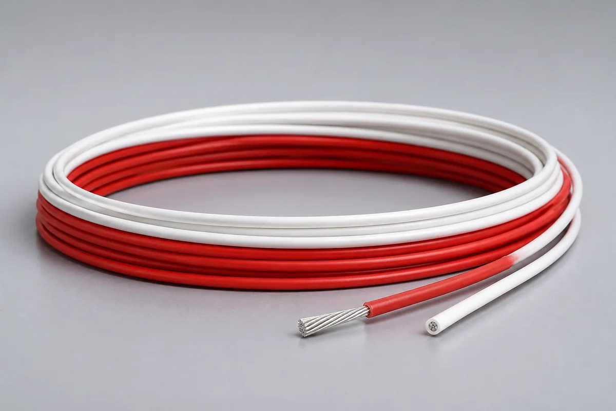
01 / CONFIGURATION DIRECTIONS
These configurations establish a practical discussion starting point. The final product requires a controlled specification based on interface, length, installation and validation conditions.
For airborne power and EWIS with mass, diameter and safety margin balanced.
For higher system voltage, thermal load and electrification needs.
Long-term stability against chemicals, humidity, abrasion and flame.
Solution codes support early technical discussions by aligning protocol, construction, link boundaries and application in one view.
MODEL NOTEAmpacity, voltage and temperature rise must be defined with gauge, length, altitude, bundling, cooling and termination conditions.
02 / PERFORMANCE PARAMETERS
The following values describe current product performance boundaries, with the applicable model, construction or test condition retained.
Sea-level withstand and PD condition
Comparative direction versus common insulation
Low-permittivity, hydrophobic, non-hydrolyzing direction
Material characteristic
Material characteristic
Test standards
The 600 Vrms direction is based on sea-level voltage-withstand and partial-discharge performance; final capability depends on gauge and environment.
03 / TYPICAL CONSTRUCTION
Gauge, stranding and plating are selected for resistance, flex and termination.
Thin-wall high-temperature material establishes voltage, PD and abrasion margin.
Grading, shielding and return paths are added for high-voltage or EMI needs.
Tapes, braid or jacket improve cut-through, wear and installation durability.
Crimp, solder, connector and thermal-cycle interfaces are controlled together.
04 / SELECTION & VALIDATION
Continuous/peak voltage, current, frequency and partial-discharge boundary
Length, conductor section, resistance and allowable voltage drop
Ambient, bundling, cooling and temperature rise
Diameter, mass, bend radius, vibration and abrasion
Fluids, humidity, flame, smoke/toxicity or vacuum
Terminal, crimp window, connector and strain relief
Ampacity, voltage and temperature rise must be defined with gauge, length, altitude, bundling, cooling and termination conditions.
Ready to define a controlled specification?
Yidong Telecom can build a sample direction and validation matrix around the cable construction, termination and system boundaries.
Submit requirement checklist ↗