Single bus pair
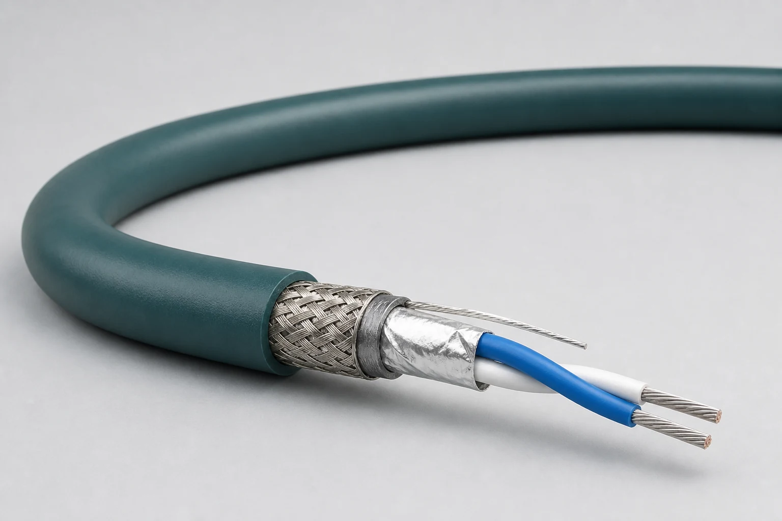
A compact shielded or unshielded pair for a primary CAN channel.

DATA / CAN / 05
120-ohm controlled shielded twisted-pair links for aerospace, vehicle and industrial control networks, defined around CAN / CAN FD topology, common-mode noise, termination, node count and rugged routing.
01 / CONFIGURATION DIRECTIONS
These configurations establish a practical discussion starting point. The final product requires a controlled specification based on interface, length, installation and validation conditions.
A compact shielded or unshielded pair for a primary CAN channel.
Two controlled pairs combined for dual-channel or fault-tolerant system architecture.
CAN pairs combined with power, discretes or other signals in one cable while managing coupling.
Solution codes support early technical discussions by aligning protocol, construction, link boundaries and application in one view.
MODEL NOTESolution codes support topology and construction discussions; they do not replace complete network design. Final part number must account for node count, trunk and stub length, termination and connectors.
02 / PERFORMANCE PARAMETERS
The following values describe current product performance boundaries, with the applicable model, construction or test condition retained.
CAN bus construction
Nominal value
System operating condition
Typical transmission values
Typical value
Conductor-conductor; version dependent
Standard versions
Ultralight 24 AWG, DXN2657-24
Dielectric withstand and weight vary between standard and ultralight versions; the applicable construction is identified for each value.
03 / TYPICAL CONSTRUCTION
Resistance and size support network length, voltage margin and termination.
Defines pair spacing and dielectric behavior.
Supports impedance balance and common-mode rejection.
Configured from EMC zone, grounding and connector design.
Matches vehicle, aerospace or industrial installation loads.
04 / SELECTION & VALIDATION
CAN, CAN FD or project-specific physical layer
Bus length, stubs, node count and termination scheme
Target rate and timing margin
Unshielded, shielded, drain and shell termination
Diameter, bend, flex, vibration and abrasion
Temperature, fluids, flame and platform requirements
Bus length, stub length, bit rate and EMC capability are system properties and must be validated with the actual nodes and termination network.
Ready to define a controlled specification?
Yidong Telecom can build a sample direction and validation matrix around the cable construction, termination and system boundaries.
Submit requirement checklist ↗