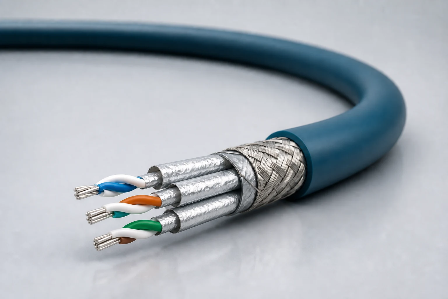
Cat 8 four-pair
For short high-throughput equipment links up to 40 Gb/s, with pair-to-pair crosstalk, return loss and high-frequency insertion-loss budget controlled together.

DATA / ETH / 01
Controlled-impedance interconnects for avionics, mission equipment, high-speed vision and precision industrial networks, spanning Cat 5e, Cat 6A and Cat 8 directions with insertion loss, return loss, crosstalk and skew managed as a complete channel.
01 / CONFIGURATION DIRECTIONS
These configurations establish a practical discussion starting point. The final product requires a controlled specification based on interface, length, installation and validation conditions.
For short high-throughput equipment links up to 40 Gb/s, with pair-to-pair crosstalk, return loss and high-frequency insertion-loss budget controlled together.
For avionics backbones, vision and mission networks up to 10 Gb/s, balancing transmission performance, diameter and mass.
For two-pair protocols and space-constrained equipment links, reducing conductor count, diameter and mass while supporting frequency directions up to 1 GHz.
A 100-ohm symmetrical quad for aerospace connector systems; indicative link directions are 70 m for 24 AWG and 50 m for 26 AWG.
Solution codes support early technical discussions by aligning protocol, construction, link boundaries and application in one view.
MODEL NOTEThese codes support solution discussions and requirement capture; they are not released standard part numbers. Final part number, dimensional tolerances and inspection requirements are frozen in the approved drawing and technical specification.
02 / PERFORMANCE PARAMETERS
The following values describe current product performance boundaries, with the applicable model, construction or test condition retained.
Cat 8 four-pair construction
Cat 5e / Cat 6A four-pair construction
Cat 5e two-pair construction
Cat 5e Quadrax; 24 AWG / 26 AWG
Full configuration range
Ultralight Cat 6A, 24 AWG, RCN9265-24
Limits vary by category, gauge and part number; confirm each value against the target link configuration.
03 / TYPICAL CONSTRUCTION
Gauge, plating and stranding are selected for flex, strength, resistance and termination.
Dielectric material and wall thickness control target impedance, delay and attenuation.
Lay length, pair roundness and pair-to-pair consistency are managed.
Foil, braid and drain paths are configured for crosstalk, EMI and grounding strategy.
Matched to temperature, flame, abrasion, marking and connector strip dimensions.
04 / SELECTION & VALIDATION
Cat5e, Cat6A, Cat8 or project-defined link target
2-pair, 4-pair, symmetrical quad, point-to-point or backbone
Cable length, connector count and allowable insertion-loss budget
Diameter, mass, bend radius and routing channel
Temperature, vibration, abrasion, fluids, flame or vacuum
Circular, rectangular, modular or pigtail interface
Protocol class, data rate and channel distance are confirmed only after validation of the final cable construction, connectors and complete channel.
Ready to define a controlled specification?
Yidong Telecom can build a sample direction and validation matrix around the cable construction, termination and system boundaries.
Submit requirement checklist ↗