22 AWG extended-distance type
Larger conductor section for power-drop and longer-link requirements.

DATA / 1394 / 09
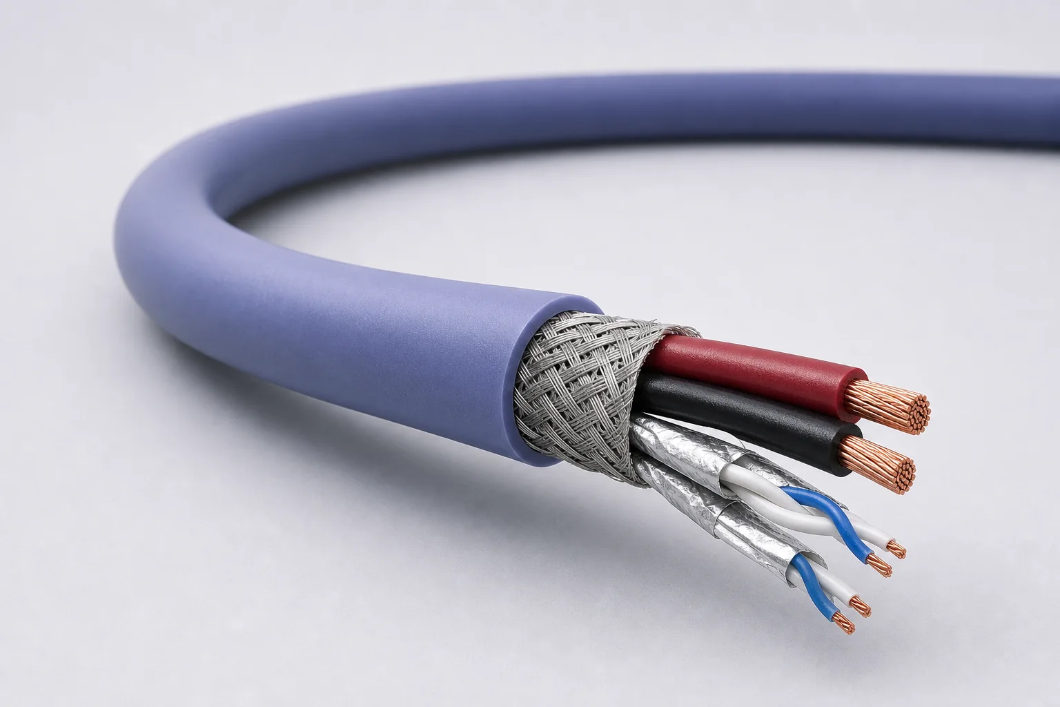
110-ohm data-and-power cable for IEEE 1394b / AS5643-class airborne and vehicle networks through 400 Mb/s, with 22, 24 and 26 AWG directions that balance voltage drop, mass and routing space.
01 / CONFIGURATION DIRECTIONS
These configurations establish a practical discussion starting point. The final product requires a controlled specification based on interface, length, installation and validation conditions.
Larger conductor section for power-drop and longer-link requirements.
Balances mass, diameter, termination and aerospace routing.
For dense, short or mass-sensitive equipment links.
Solution codes support early technical discussions by aligning protocol, construction, link boundaries and application in one view.
MODEL NOTEThe 22, 24 and 26 AWG directions represent separate constructions. Final part number is determined with bus length, nodes, supply current, voltage drop, connectors and shield grounding.
02 / PERFORMANCE PARAMETERS
The following values describe current product performance boundaries, with the applicable model, construction or test condition retained.
IEEE 1394b / AS5643 direction
Nominal value
System operating condition
Nominal values
Typical values
Conductor-conductor / conductor-shield
Full family
The 22, 24 and 26 AWG sizes are separate part numbers; transmission values cover the family.
03 / TYPICAL CONSTRUCTION
Gauge, voltage drop, strength and termination contacts define the conductor construction.
Expanded PTFE/PTFE controls impedance, delay and high-frequency attenuation.
Differential pairs, quads or multichannel video/data units are formed around the protocol.
Pair coupling, external EMI and connector return continuity are managed together.
Wide temperature, abrasion, flame, marking and harness termination are balanced.
04 / SELECTION & VALIDATION
Interface revision, target rate, encoding and maximum channel length
Impedance, insertion/return loss, skew and dielectric withstand
Pair count, auxiliary wires, power and shield zoning
Gauge, diameter, mass, bend radius and harness section
Temperature, vibration, abrasion, fluids, smoke/toxicity and flame
Connector, contact, backshell, grounding and strain relief
Data rate and channel capability depend on the final cable, length, connectors and termination process and must be confirmed as a complete channel.
Ready to define a controlled specification?
Yidong Telecom can build a sample direction and validation matrix around the cable construction, termination and system boundaries.
Submit requirement checklist ↗