24 AWG ultralight
A 3.30 mm diameter, 16.2 mm minimum bend radius and 12.8 g/m direction for smaller, lighter equipment harnesses.

DATA / STP / 02
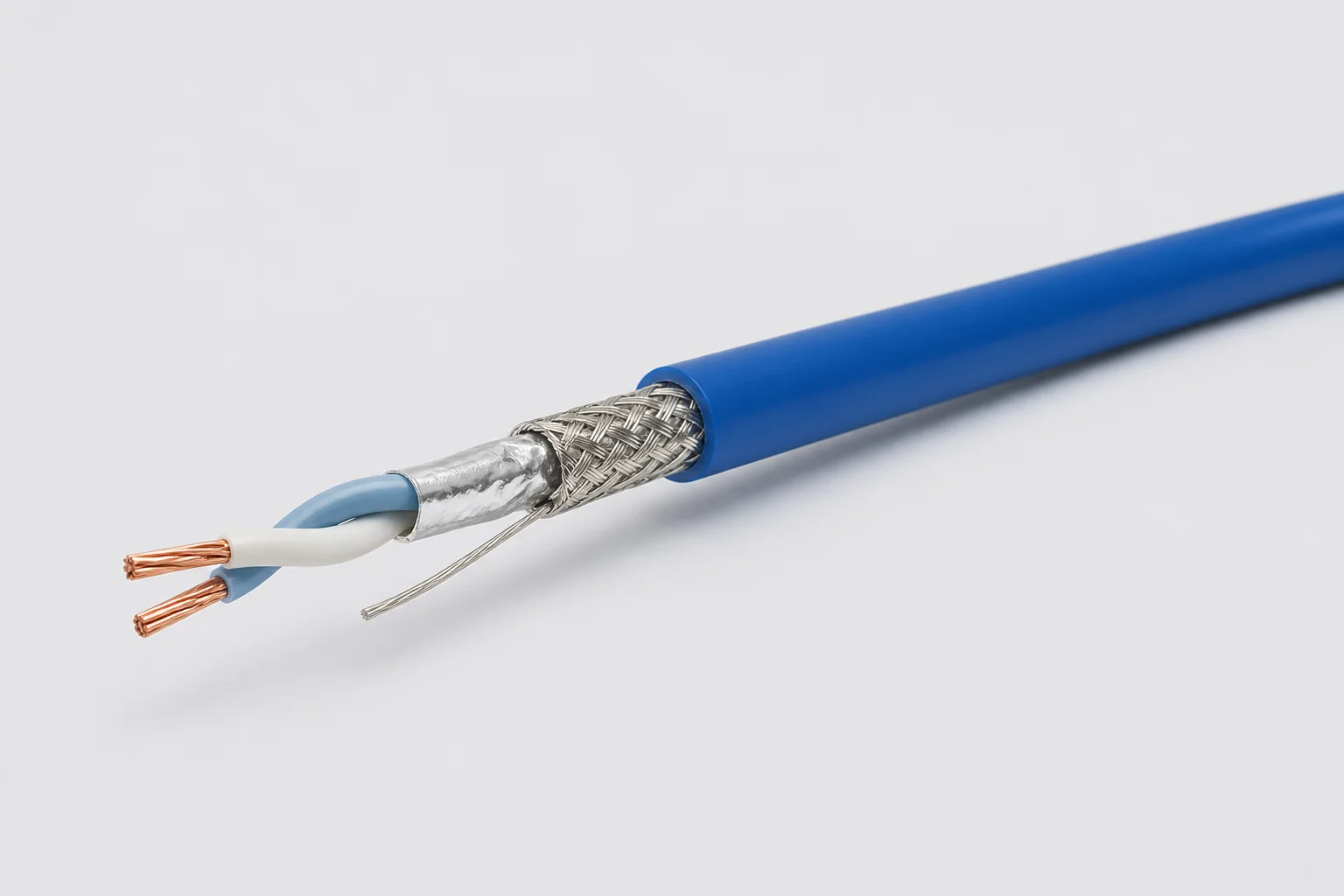
100-ohm single-pair shielded cable for aerospace, vehicle and precision-equipment differential links through 1 GHz, using controlled twist, foil, braid and drain paths to manage impedance, common-mode noise and wide-temperature reliability.
01 / CONFIGURATION DIRECTIONS
These configurations establish a practical discussion starting point. The final product requires a controlled specification based on interface, length, installation and validation conditions.
A 3.30 mm diameter, 16.2 mm minimum bend radius and 12.8 g/m direction for smaller, lighter equipment harnesses.
Maintains differential geometry, dielectric withstand and shield continuity from −65 to +200 °C.
For softer equipment routing; temperature, flame and fluid compatibility are confirmed by configuration.
Solution codes support early technical discussions by aligning protocol, construction, link boundaries and application in one view.
MODEL NOTESolution codes support early impedance, gauge and environment matching. Final part number, jacket material, shield termination, connectors and complete-channel performance are confirmed in the technical specification.
02 / PERFORMANCE PARAMETERS
The following values describe current product performance boundaries, with the applicable model, construction or test condition retained.
Shielded twisted-pair construction
Nominal value
System operating condition
Typical transmission values
Typical value
Conductor-conductor / conductor-shield
Fluoropolymer version
Ultralight 24 AWG, DXN2656-24
Electrical and mechanical values apply to the fluoropolymer STP construction; polyurethane versions have a different temperature range.
03 / TYPICAL CONSTRUCTION
Conductor size and resistance balance are controlled for the receiving interface.
Material and concentricity establish dielectric behavior and pair geometry.
Lay length balances flexibility, common-mode behavior and pair stability.
Shield coverage, drain and grounding are selected from the EMI zone.
Provides abrasion, environmental protection and termination support.
04 / SELECTION & VALIDATION
Target impedance, data rate, voltage and common-mode range
Single pair, multi-pair or mixed-signal construction
Individual, overall or combined shields and grounding
Round, low-profile, fixed, flexing or torsional
Temperature, vibration, fluids, flame and cleanliness
Connector contacts, backshell, drain and strip dimensions
Frequency, impedance, shielding and protocol capability depend on the complete pair, connector and grounding implementation and require channel validation.
Ready to define a controlled specification?
Yidong Telecom can build a sample direction and validation matrix around the cable construction, termination and system boundaries.
Submit requirement checklist ↗