75-ohm high-bandwidth video coax
For digital video, cameras, displays and precision measurement links through 12 GHz.

DATA / COAX / 03
Precision concentric transmission paths for video, timing, instrumentation and sensitive single-ended signals, spanning 50- and 75-ohm directions with frequency, loss, shielding and connector transitions defined as a complete assembly.
01 / CONFIGURATION DIRECTIONS
These configurations establish a practical discussion starting point. The final product requires a controlled specification based on interface, length, installation and validation conditions.
For digital video, cameras, displays and precision measurement links through 12 GHz.
For timing, sensing, instrumentation and equipment-module links through 3 GHz.
Reduces diameter and mass inside equipment, multi-coax connectors and dense assemblies.
Solution codes support early technical discussions by aligning protocol, construction, link boundaries and application in one view.
MODEL NOTESolution codes support early impedance, frequency and installation matching. Final part number, attenuation curve, dimensions and connector transition are frozen after assembly specification approval.
02 / PERFORMANCE PARAMETERS
The following values describe current product performance boundaries, with the applicable model, construction or test condition retained.
75 Ω version
75 Ω version
75 Ω version
75 Ω; shielding through 2 MHz
50 Ω version
50 Ω version
50 Ω version
50 Ω and 75 Ω versions
The 50 Ω and 75 Ω constructions are separate configurations; values are listed against the applicable impedance version.
03 / TYPICAL CONSTRUCTION
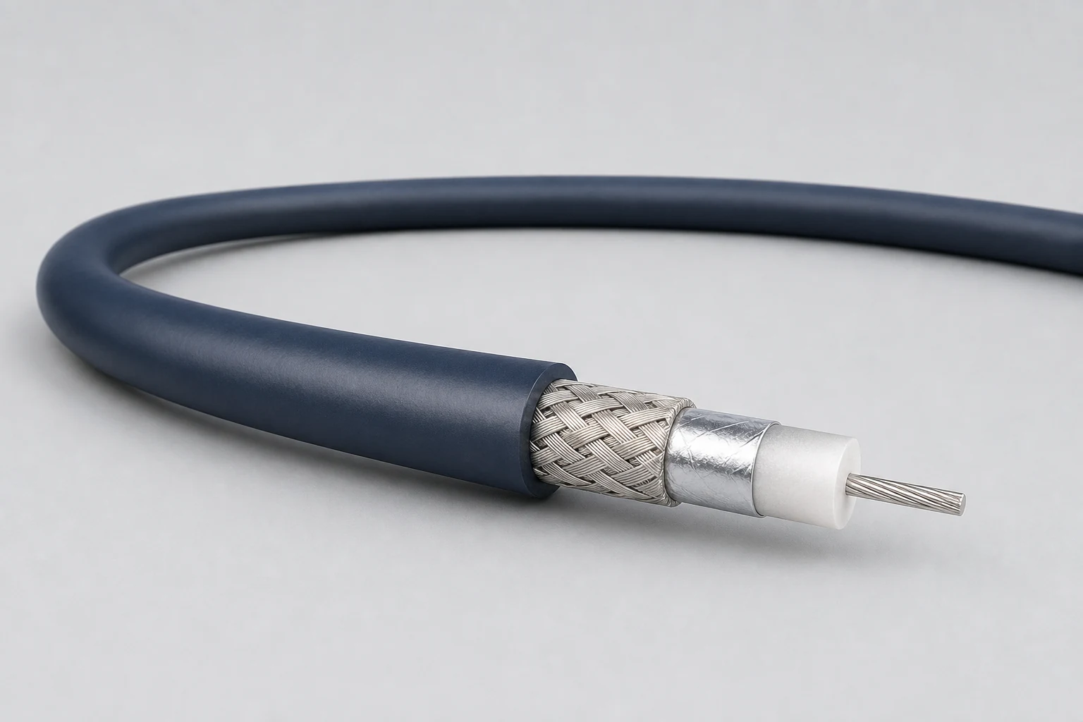
Solid or stranded geometry selected for attenuation, flexibility and termination.
Concentric low-loss insulation establishes impedance and electrical length.
Foil, braid or composite return path provides shielding and mechanical stability.
Protects the coax while controlling diameter, friction and bend behavior.
Termination geometry is treated as part of the impedance-controlled path.
04 / SELECTION & VALIDATION
50 Ω, 75 Ω or project-defined target
Highest frequency, edge rate and link budget
Assembly length, tolerance and connector transitions
Outer diameter, bend radius and motion
Coverage, leakage target and grounding
Cable-end connector, board transition or bundled harness
Impedance and loss values are established for a defined cable size, length, frequency range and connector configuration.
Ready to define a controlled specification?
Yidong Telecom can build a sample direction and validation matrix around the cable construction, termination and system boundaries.
Submit requirement checklist ↗