24 AWG low-crosstalk type
A larger conductor section for loss, mechanical strength and tighter impedance requirements.

DATA / QUAD / 11
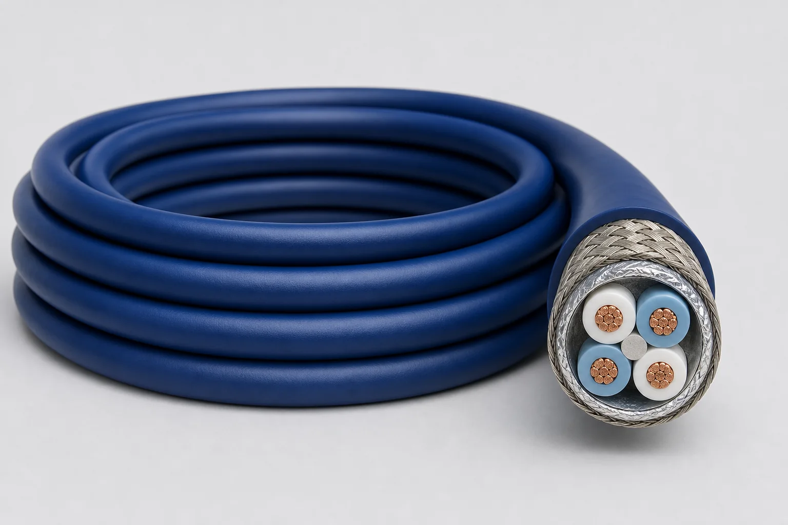
Symmetrical quad geometry organizes two balanced differential signals in one cable across 24, 26 and 28 AWG directions through 1 GHz, with a compact cross-section delivering about 40% size reduction and up to 30% lower mass.
01 / CONFIGURATION DIRECTIONS
These configurations establish a practical discussion starting point. The final product requires a controlled specification based on interface, length, installation and validation conditions.
A larger conductor section for loss, mechanical strength and tighter impedance requirements.
Balances frequency, diameter, mass, termination and airborne connector fit.
For short high-speed box links on mass- and routing-constrained platforms.
Solution codes support early technical discussions by aligning protocol, construction, link boundaries and application in one view.
MODEL NOTEThe 100-ohm tolerance, capacitance and delay vary by construction. Solution codes support gauge and installation matching; final part number, length, connectors and complete-channel performance are confirmed to system requirements.
02 / PERFORMANCE PARAMETERS
The following values describe current product performance boundaries, with the applicable model, construction or test condition retained.
24 / 26 / 28 AWG
By part number
Full family
By part number
By part number
Versus two twisted-pair cables
Full family
RCN8752, RCN8982 and RCN8973 differ slightly in impedance and capacitance; family ranges are shown.
03 / TYPICAL CONSTRUCTION
Gauge, voltage drop, strength and termination contacts define the conductor construction.
Expanded PTFE/PTFE controls impedance, delay and high-frequency attenuation.
Differential pairs, quads or multichannel video/data units are formed around the protocol.
Pair coupling, external EMI and connector return continuity are managed together.
Wide temperature, abrasion, flame, marking and harness termination are balanced.
04 / SELECTION & VALIDATION
Interface revision, target rate, encoding and maximum channel length
Impedance, insertion/return loss, skew and dielectric withstand
Pair count, auxiliary wires, power and shield zoning
Gauge, diameter, mass, bend radius and harness section
Temperature, vibration, abrasion, fluids, smoke/toxicity and flame
Connector, contact, backshell, grounding and strain relief
Data rate and channel capability depend on the final cable, length, connectors and termination process and must be confirmed as a complete channel.
Ready to define a controlled specification?
Yidong Telecom can build a sample direction and validation matrix around the cable construction, termination and system boundaries.
Submit requirement checklist ↗